Hydrogen energy engineering
- Home
- Hydrogen energy engineering
Our approach to hydrogen energy, examples
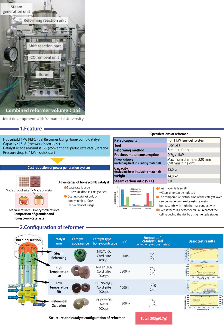
Combined type reformer
In the development of a reformer for household fuel cell systems, we developed a 1 kw class PEFC reformer in collaboration with a university, and at that time developed the world’s smallest class combined reformer.
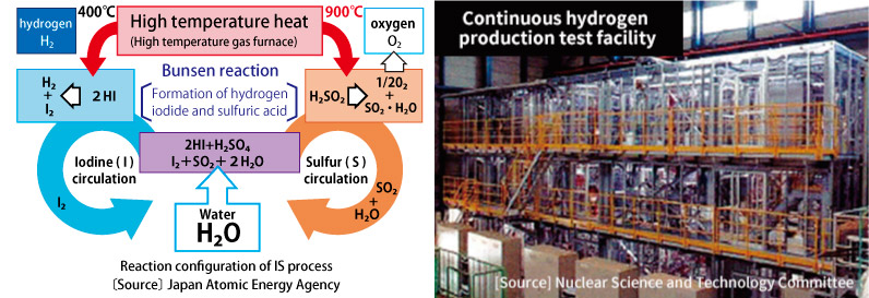
Continuous hydrogen production test facility by IS process
Fiscal 2013 (National Institute of Advanced Industrial Science and Technology) Japan National Institute for Nuclear Research and Development, Oarai Research and Development Center, a continuous hydrogen by IS process that decomposes water by thermal energy to generate hydrogen and oxygen using chemical reaction with sulfuric acid and hydrogen iodide. We have delivered a production test facility.
Principle of
IS process The IS process is a chemical process that decomposes water by combining three thermochemical reactions using compounds of iodine (I) and sulfur (S). Hydrogen and oxygen are produced by the decomposition of sulfuric acid and hydrogen iodide using the heat of 300 to 900 ° C supplied from the high temperature gas furnace. A major feature is the closed cycleability, in which reactive substances such as iodine and sulfuric acid other than water are repeatedly used in the process. ([Source] (National Institute of Advanced Industrial Science and Technology) Japan Atomic Energy Agency)
Ammonia synthesis test facility
In fiscal 2017 (National Institute of Advanced Industrial Science and Technology), we delivered an ammonia synthesis test facility for testing new catalysts for ammonia synthesis to the Fukushima Renewable Energy Research Center.
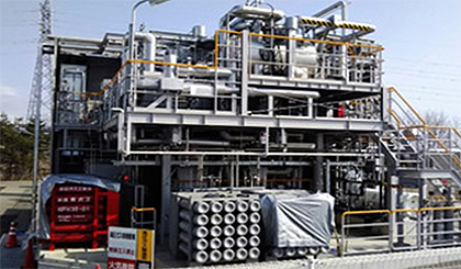 At AIST, in order to realize the synthesis of ammonia (re-energy ammonia) from hydrogen (re-energy hydrogen) produced using renewable energy, it overcomes the problem specific to ruthenium catalyst, which lowers its performance with increasing pressure And created a new catalyst capable of maintaining high activity in a pressure range of 10 MPa (about 100 atm) or less. The process developed by JGC Corporation using this catalyst makes it possible to produce ammonia from re-energized hydrogen with variable supply amount, and a demonstration test device equipped with this catalyst has been constructed at the Fukushima Renewable Energy Research Institute. The demonstration test started in earnest. Ammonia is expected as an energy carrier because it is useful as a hydrogen storage material and can be transported in large quantities, and furthermore, ammonia itself is used as a fuel that does not emit carbon dioxide (CO2 ) at the time of combustion . ([Source] (Country) National Institute of Advanced Industrial Science and Technology)
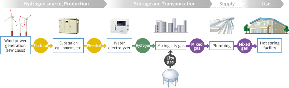
Hydrogen mixed gas supply utilization demonstration project
In the fiscal 2018 and 2019, we are promoting the production and storage of re-generated electrolytic hydrogen and the supply and utilization of hydrogen mixed gas of the Ministry of the Environment. It mixes hydrogen from LPG reforming and water electrolysis equipment to produce gas with heat equivalent to city gas. The manufactured gas is sent to a simulated house and burned with commercially available gas appliances.
Outline of Demonstration Project
Produces hydrogen by wind power generation and mixes it with gas close to city gas. The mixed gas is supplied by gas piping to a use site installed at an adjacent site, and a hydrogen mixed gas is actually used in a commercial gas apparatus.
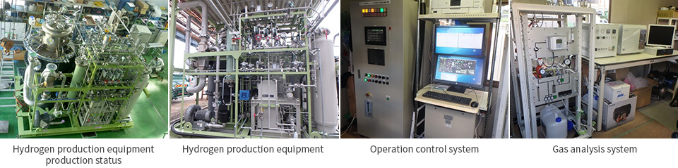
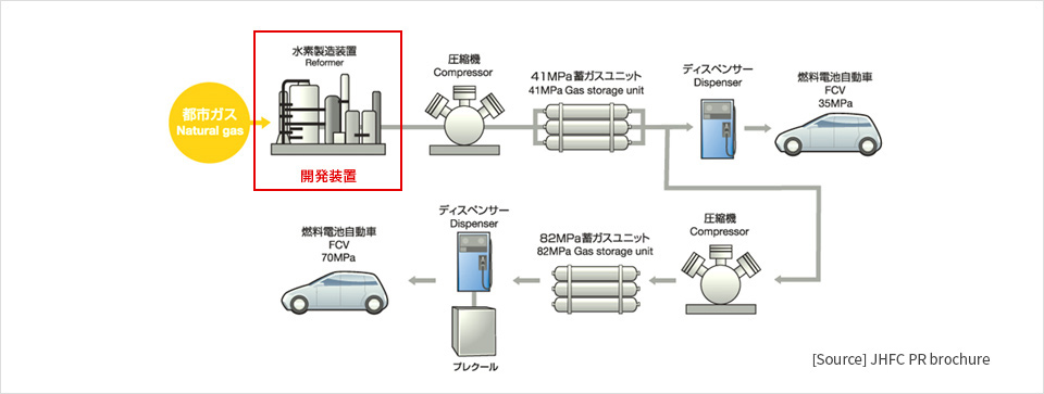
Hydrogen station cost reduction
At present, for on-site hydrogen station hydrogen production equipment, development is under way to reduce the cost of the equipment to 50 million yen or less in order to spread FCV scheduled from fiscal 2015. However, in the conventional hydrogen production apparatus, it is considered that further technical development is necessary to achieve the price target because of the large number of instruments constituting the apparatus.
In fiscal 2013, in fiscal 2013 NEDO (National Research and Development Corporation New Energy and Industrial Technology Development Organization) [R & D on hydrogen technology and development of low-cost equipment and systems for fuel cell vehicles and hydrogen stations] Development of low-cost hydrogen production equipment), and by installing a combined reformer that integrates [Steam Reformer], [CO Converter], and [Steam Generator] into the hydrogen production equipment , We have developed a small-sized, low-cost hydrogen production system that reduces the number of devices that make up the hydrogen production system to less than half that of the conventional hydrogen production system, and has developed it for the purpose of contributing to the spread of FCV.
Target cost of hydrogen production equipment: Achieve 50 million yen or less. (100 Nm3 / h)
About city gas reformed hydrogen supply equipment
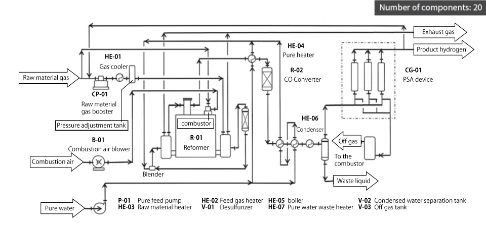
Hydrogen production system system flow equipped with conventional reformer (reference)
Hydrogen production system system flow equipped with combined reformer
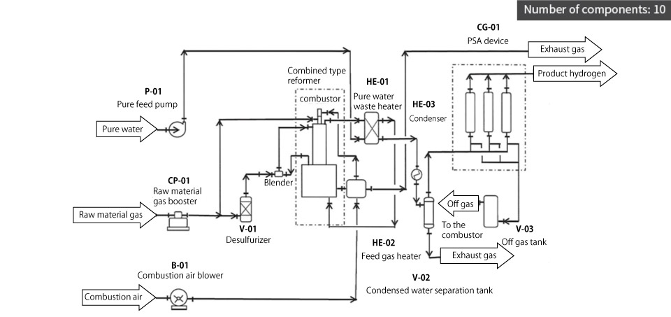
Type and structure of combined reformer
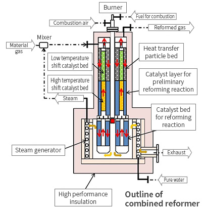
- The raw material gas is mixed with steam in the mixer and heated while absorbing the reaction heat of the low temperature shift when passing through the heat transfer particle layers provided on the inside and the outside of the low temperature shift reaction catalyst layer (exothermic reaction).
- Furthermore, when passing through the prereforming reaction catalyst layer (endothermic reaction) provided on the inside and the outside of the high temperature shift reaction catalyst layer (exothermic reaction), the heated source gas absorbs the reaction heat of the high temperature shift, Partially reformed.
- The partially reformed raw material gas is main-reformed by the combustion heat from the combustor in the lower reforming reaction catalyst layer (endothermic reaction).
- The reformed gas containing CO is sent to a reformed gas purification device (PSA) with the concentration of CO reduced by passing through the high temperature / low temperature shift reaction catalyst layer.
- The steam necessary for the reforming reaction is generated by a steam generator provided outside the reforming reaction catalyst layer.
- The combustor will be installed at the center of the combined reformer, and the exterior insulation will use high-performance insulation to reduce the size of the reformer.
Verification test machine